JRD-100 - Arduino UHF-RFID Module Development
Reading time: 8 minutes
Last modified:
Efficient inventory management and secure access control are critical for many businesses. The JRD-100, a wireless ultra-high frequency (UHF) RFID tag reader, offers a powerful solution for these needs. This guide explores the JRD-100’s capabilities, applications, and integration possibilities.
What is the JRD-100?
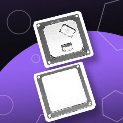
The JRD-100 is a UHF RFID tag reader designed for long-range identification. Key features include:
- 100 mW transmitter for reading tags within a 1.5+ meter radius
- Ability to read up to 50 radio tags per second
- Internal buffer capacity of 200 units
- Energy-efficient operation
Key Specifications
Here are the core specifications of the JRD-100:
- Tag reading distance: 1-2.5m
- Recording distance: 10cm
- Working voltage: 3.3 - 5V
- Operating frequency range: 840-960 MHz
- Output power: 18-26 dBm
- Interface: TTL UART
- Wireless protocol support:
- EPC Global UHF Class 1 Gen 2
- ISO 18000-6C
Applications Across Industries
The JRD-100 proves useful in various sectors:
- Warehouse Logistics: Streamline inventory management and optimize supply chains.
- Automated Retail: Enhance inventory tracking and ensure product availability.
- Accounting and Security Systems: Monitor transactions, control access to restricted areas, and improve overall security.
Real-World Use Cases
To better illustrate the JRD-100’s capabilities, let’s explore some real-world scenarios where it can solve specific problems:
1. Automotive Manufacturing: Streamlining Assembly Line Tracking
Problem: A car manufacturer struggles to track individual components through the assembly process, leading to inefficiencies and occasional errors in vehicle configuration.
Solution: By attaching UHF RFID tags to key components and installing JRD-100 readers at various points along the assembly line, the manufacturer can:
- Automatically track each component’s progress
- Ensure correct parts are used for each vehicle model
- Quickly identify and resolve any discrepancies in real-time
- Improve overall production efficiency and reduce errors
Result: The automotive manufacturer reports a 15% reduction in assembly errors and a 10% increase in production speed after implementing the JRD-100 system.
2. Retail Clothing Store: Enhancing Inventory Management and Loss Prevention
Problem: A multi-story clothing retailer faces challenges with inventory accuracy, misplaced items, and shoplifting.
Solution: By tagging all clothing items with UHF RFID tags and installing JRD-100 readers throughout the store, the retailer can:
- Conduct rapid inventory checks without manual counting
- Quickly locate misplaced items by floor and department
- Detect unauthorized item removal through strategically placed readers near exits
Result: The retailer reports a 30% reduction in inventory discrepancies, a 25% decrease in time spent on inventory management, and a 20% reduction in shrinkage due to theft.
3. Hospital: Improving Asset Tracking and Patient Safety
Problem: A large hospital struggles to keep track of valuable mobile medical equipment and ensure that sensitive patient information is only accessed by authorized personnel.
Solution: By tagging medical equipment with UHF RFID tags and providing staff with RFID-enabled ID badges, the hospital uses JRD-100 readers to:
- Track the real-time location of critical medical equipment
- Monitor equipment utilization and streamline maintenance schedules
- Control access to restricted areas and sensitive patient information
- Automatically log staff movements for security and audit purposes
Result: The hospital reports a 40% reduction in time spent searching for equipment, a 25% improvement in equipment utilization, and zero unauthorized access incidents since implementing the system.
These real-world examples demonstrate the versatility and effectiveness of the JRD-100 in solving complex tracking and identification challenges across various industries. By leveraging its long-range reading capabilities and high-speed tag processing, organizations can significantly improve their operations, security, and overall efficiency.
Technical Integration
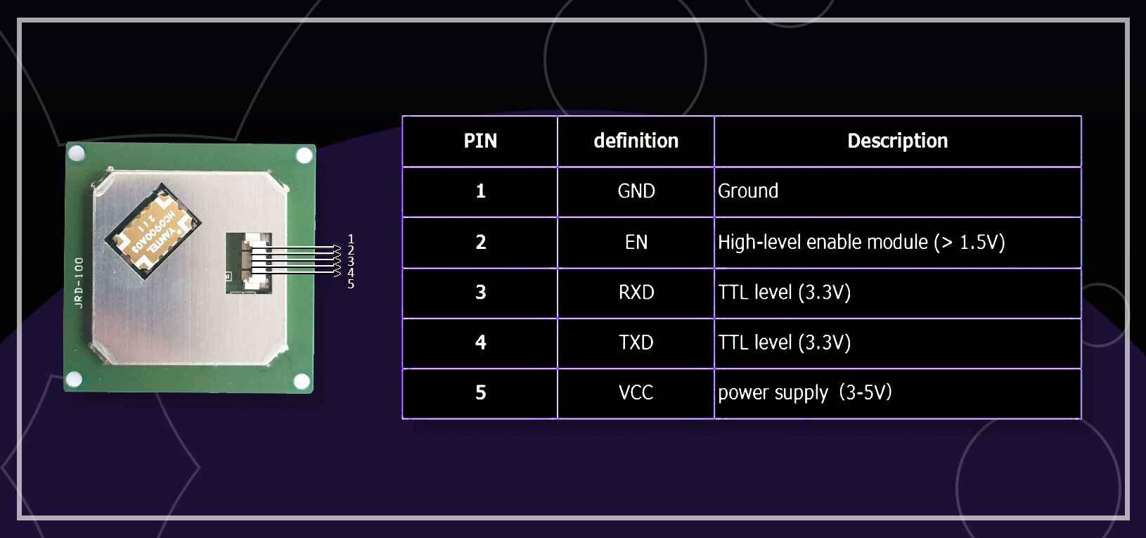
JRD-100 Pinout
For those integrating the JRD-100 into their systems, here’s the pinout:
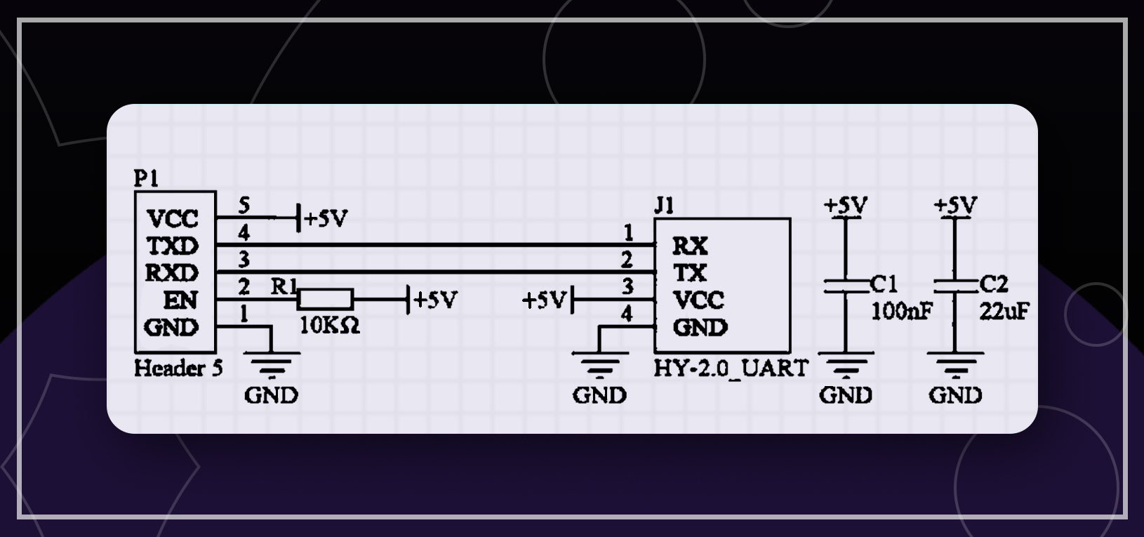
UART Connection
The JRD-100 uses a UART interface for “Plug & Play” functionality. Here’s the setup:
- Connect the EN pin to 5V
- Install a pair of capacitors for power stability
- Control data transmission using AT commands
Here’s the connection schematic:
Limitations to Consider
While the JRD-100 is a capable device, it has some limitations:
- Reading distance limited to 1-2.5 meters
- Specific voltage requirements (3.3V to 5V)
- Limited public documentation and example code
Despite these constraints, the JRD-100 remains a solid choice for many long-range identification applications.
Arduino Integration
Due to the lack of public documentation, we’ve developed our own method to integrate the JRD-100 with Arduino:
- We used an STM32F103C8T6 microcontroller
- The setup works with any Arduino board that has two Hardware Serials
- Arduino Uno users can switch to Software Serial
Code
There are no manuals and examples of module integration in the public domain, so we ourselves developed the integration of UHF-RFID JRD-100 with Arduino. We’ll use STM32F103C8T6, you can use any compatible Arduino with two Hardware Serials or switch to Software Serial using Arduino Uno.
    #include <Arduino.h>
    #include <HardwareSerial.h>

    HardwareSerial Serial2(PA3, PA2);
    bool DEBUG = true;

    const uint8_t RFID_cmdnub[][26] =
    {
      {0xBB, 0x00, 0x03, 0x00, 0x01, 0x00, 0x04, 0x7E,},       //0. Hardware version
      {0xBB, 0x00, 0x03, 0x00, 0x01, 0x01, 0x05, 0x7E,},       //1. Software version
      {0xBB, 0x00, 0x03, 0x00, 0x01, 0x02, 0x06, 0x7E,},       //2. manufacturers
      {0xBB, 0x00, 0x22, 0x00, 0x00, 0x22, 0x7E,},             //3. Single polling instruction
      {0xBB, 0x00, 0x27, 0x00, 0x03, 0x22, 0x27, 0x10, 0x83, 0x7E,}, //4. Multiple polling instructions
      {0xBB, 0x00, 0x28, 0x00, 0x00, 0x28, 0x7E,},             //5. Stop multiple polling instructions
      { 0xBB, 0x00, 0x0C, 0x00, 0x13, 0x01, 0x00, 0x00, 0x00, 0x20,
        0x60, 0x00, 0x30, 0x75, 0x1F, 0xEB, 0x70, 0x5C, 0x59, 0x04,
        0xE3, 0xD5, 0x0D, 0x70, 0xAD, 0x7E,
      },  //6. Set the SELECT parameter instruction
      {0xBB, 0x00, 0x0B, 0x00, 0x00, 0x0B, 0x7E,},              //7. Get the SELECT parameter
      {0xBB, 0x00, 0x12, 0x00, 0x01, 0x01, 0x14, 0x7E,},        //8. Set the SELECT mode
      { 0xBB, 0x00, 0x39, 0x00, 0x09, 0x00, 0x00, 0x00, 0x00, 0x03,
        0x00, 0x00, 0x00, 0x08, 0x4D, 0x7E,
      }, //9. Read label data storage area
      { 0xBB, 0x00, 0x49, 0x00, 0x11, 0x00, 0x00, 0x00, 0x00, 0x03,
        0x00, 0x00, 0x00, 0x04, 0x22, 0x22, 0x22, 0x22, 0x22, 0x22, 0x22, 0x22, 0x71, 0x7E
      },   //10. Write the label data store
      { 0xBB, 0x00, 0x82, 0x00, 0x07, 0x00, 0x00, 0xFF,
        0xFF, 0x02, 0x00, 0x80, 0x09, 0x7E,
      },  //11. Lock the LOCK label data store
      { 0xBB, 0x00, 0x65, 0x00, 0x04, 0x00, 0x00, 0xFF, 0xFF, 0x67,
        0x7E,
      }, //12. Inactivate the kill tag
      {0xBB, 0x00, 0x11, 0x00, 0x02, 0x00, 0xC0, 0xD3, 0x7E,}, //13. Set communication baud rate
      {0xBB, 0x00, 0x0D, 0x00, 0x00, 0x0D, 0x7E,},            //14. Get parameters related to the Query command
      {0xBB, 0x00, 0x0E, 0x00, 0x02, 0x10, 0x20, 0x40, 0x7E,}, //15. Set the Query parameter
      {0xBB, 0x00, 0x07, 0x00, 0x01, 0x01, 0x09, 0x7E,},      //16. Set up work area
      {0xBB, 0x00, 0x08, 0x00, 0x00, 0x08, 0x7E,},            //17. Acquire work locations
      {0xBB, 0x00, 0xAB, 0x00, 0x01, 0x01, 0xAC, 0x7E,},      //18. Set up working channel
      {0xBB, 0x00, 0xAA, 0x00, 0x00, 0xAA, 0x7E,},            //19. Get the working channel
      {0xBB, 0x00, 0xAD, 0x00, 0x01, 0xFF, 0xAD, 0x7E,},      //20. Set to automatic frequency hopping mode
      { 0xBB, 0x00, 0xA9, 0x00, 0x06, 0x05, 0x01, 0x02,
        0x03, 0x04, 0x05, 0xC3, 0x7E,
      },                             //21. Insert the working channel
      {0xBB, 0x00, 0xB7, 0x00, 0x00, 0xB7, 0x7E,},            //22. Acquire transmitting power
      {0xBB, 0x00, 0xB6, 0x00, 0x02, 0x07, 0xD0, 0x8F, 0x7E,}, //23. Set the transmitting power
      {0xBB, 0x00, 0xB0, 0x00, 0x01, 0xFF, 0xB0, 0x7E,},      //24. Set up transmitting continuous carrier
      {0xBB, 0x00, 0xF1, 0x00, 0x00, 0xF1, 0x7E,},            //25. Gets the receiving demodulator parameters
      {0xBB, 0x00, 0xF0, 0x00, 0x04, 0x03, 0x06, 0x01, 0xB0, 0xAE, 0x7E,}, //26. Set the receiving demodulator parameters
      {0xBB, 0x00, 0xF2, 0x00, 0x00, 0xF2, 0x7E,},            //27. Test the RF input block signal
      {0xBB, 0x00, 0xF3, 0x00, 0x00, 0xF3, 0x7E,},            //28. Test the RSSI signal at the RF input
      {0x00},
      {0xBB, 0x00, 0x17, 0x00, 0x00, 0x17, 0x7E,},            //30. Module hibernation
      {0xBB, 0x00, 0x1D, 0x00, 0x01, 0x02, 0x20, 0x7E,},      //31. Idle hibernation time of module
      {0xBB, 0x00, 0x04, 0x00, 0x03, 0x01, 0x01, 0x03, 0x0C, 0x7E,}, //32. The IDLE mode
      {0xBB, 0x00, 0xE1, 0x00, 0x05, 0x00, 0x00, 0xFF, 0xFF, 0x00, 0xE4, 0x7E,}, //33.NXP G2X label supports ReadProtect/Reset ReadProtect command
      {0xBB, 0x00, 0xE3, 0x00, 0x05, 0x00, 0x00, 0xFF, 0xFF, 0x01, 0xE7, 0x7E,}, //34. The NXP G2X label supports the CHANGE EAS directive
      {0xBB, 0x00, 0xE4, 0x00, 0x00, 0xE4, 0x7E,},            //35. The NXP G2X tag supports the EAS_ALARM directive
      {0xBB, 0x00, 0xE0, 0x00, 0x06, 0x00, 0x00, 0xFF, 0xFF, 0x00, 0x00, 0xE4, 0x7E,}, //36.NXP G2X label 16bits config-word
      { 0xBB, 0x00, 0xE5, 0x00, 0x08, 0x00, 0x00, 0xFF, 0xFF, 0x01, 0x01, 0x40, 0x00, 0x2D, 0x7E,},//37.Impinj Monza 4 Qt tags support Qt instructions
      { 0xBB, 0x00, 0xD3, 0x00, 0x0B, 0x00, 0x00, 0xFF,
        0xFF, 0x01, 0x03, 0x00, 0x00, 0x01, 0x07, 0x00, 0xE8, 0x7E,
      },   //38.The BlockPermalock directive permanently locks blocks of a user's Block

    };

    void uhf_command(uint8_t com_nub)
    {
      uint8_t b = 0;
      while (RFID_cmdnub[com_nub][b] != 0x7E)
      {
        Serial2.write(RFID_cmdnub[com_nub][b]);
        if(DEBUG) {
          Serial.print(" 0x");
          Serial.print(RFID_cmdnub[com_nub][b], HEX);
        }
        b++;
      }
      Serial2.write(0x7E);
      Serial2.write("\n\r");
      Serial.println();
    }
    uint8_t DATA_I[256];

    void uhf_read()
    {
      uint8_t DATA_I_NUB = 0;
      while(!Serial2.available());
      while (Serial2.available())
      {
        delay(2);
        DATA_I[DATA_I_NUB] = Serial2.read();
        if (DEBUG == 1)
        {
          if(DATA_I[DATA_I_NUB] < 16) {
            Serial.print(" 0x0");
          } else {
            Serial.print(" 0x");
          }
          Serial.print(DATA_I[DATA_I_NUB], HEX);
        }
        DATA_I_NUB++;
      }
      Serial.println();
    }
    /* code */
    void setup() {
      // put your setup code here, to run once:
      Serial.begin(115200);
      Serial.println("UHF Reader");
      Serial2.begin(115200);

    }

    void loop() {
      for (size_t i = 0; i < 10; i++) {
        Serial.println("Single polling:");
        uhf_command(3);
        Serial.println("Receiving:");
        uhf_read();
        // Serial.println();
        Serial.println("Requesting data:");
        uhf_command(9);
        Serial.println("Receiving data:");
        uhf_read();
        delay(3000);
        Serial.println();
      }
    }
Conclusion
The JRD-100 UHF RFID tag reader offers a robust solution for businesses needing efficient long-range identification systems. Its high reading capacity, accuracy, and sensitivity make it suitable for various applications, from warehouse management to security systems.
By understanding its capabilities and limitations, you can determine if the JRD-100 fits your project needs. Whether you’re improving your supply chain or enhancing security measures, the JRD-100 provides a reliable and efficient solution for RFID applications.
We’ll be sharing more detailed guides on integrating the JRD-100 with various systems and exploring its potential in different industries. Stay tuned!
If you’re integrating RFID, GPS, or other hardware into a product, CimpleO builds complete IoT solutions — from embedded firmware and PCB design to cloud backend. Tell us about your project.