A9G GSM/GPS Module Guide: Pinout, AT Commands & Setup
Reading time: 6 minutes
Last modified:
IoT devices mainly use AVP, ESP and STM32 microcontrollers. To connect GSM or GPRS, you have to connect separated submodules, which greatly clutters up the final device. Not everyone knows that there is such a module as A9G gps tracker. It has a compact SMD housing that combines GSM and GPRS modules. All that remains when working with it is to connect the antennas and power. The module can be controlled using AT commands from another microcontroller or through its own SDK firmware. The A9G arduino module is developed by Ai Thinker, which is also a manufacturer of ESP microcontrollers.
In this guide, I will try to briefly explain the first steps to work with the A9G with GSM, GPS, GPRS modules. I will install the necessary software and try to control it using AT commands.
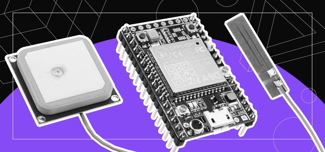
The photo shows that in my case GPS and GSM antennas are connected, and a SIM card is installed(on the backside).
First you need:
- A9G module.
- GSM antenna.
- GPS antenna.
- SIM card.
- TTL converter.
- Windows or Linux PC.
If all the components are present, download the program to control the module using AT commands: Download
At the first steps of learning a new device, you need to try all of its functionality. The module comes with firmware that allows you to accept AT commands and process them. We connect the module via a TTL converter (mine is based on the CH340G chip)
| TTL | -> | A9G |
|---|---|---|
| RX | -> | TX |
| TX | -> | RX |
| 5V | -> | VUSB |
| GND | -> | GND |
Make sure to connect everything correctly. In addition to the RX and TX connectors, the module has HST_RX and HST_TX connectors. They are intended for downloading firmware and further debugging.
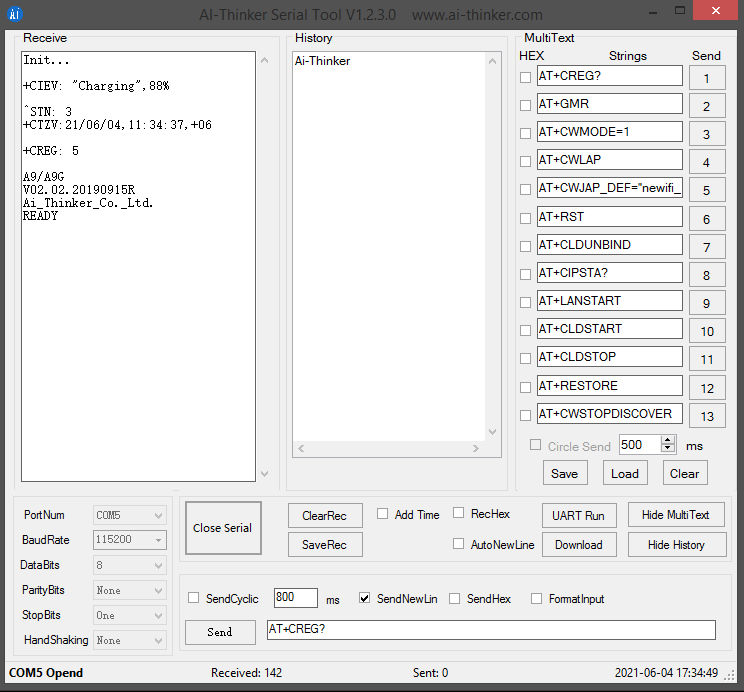
Run the program and open Serial port. Press the RESET button on the module itself and wait for the module to initialize.
The program interface is intuitive, but I have marked each zone and described it
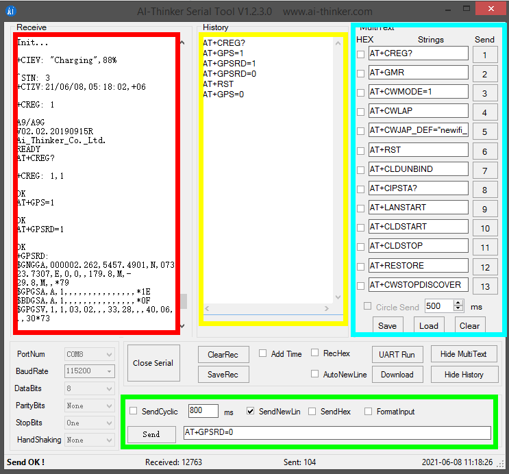
- The result of the command execution comes in a red frame.
- In green - a window for entering commands.
- In yellow - the history of commands is saved.
- In blue - a set of shortcut commands.
The module works out of the box. It is possible to receive AT commands and process them without reflashing. Do not forget to connect GSM and/or GPS antennas for the first test.
GSM commands
The A9G module has GSM capabilities with the help of which it can be used to start a call, receive a call, and send an SMS as well when we dial the number whose SIM card is inserted within the A9G module a “RING” message will continuously appear on the monitor. The AT Commands which can be used for calling and sending SMS using the A9G are:
Call Commands:
- ATA: Used to Answer an Incoming Call. On sending this command “+CIEV: “CALL”,1 CONNECT”; the message is received.
- ATD: This Command is used to dial a number this command is sent as “AT+number to be dialed” and on sending this command we receive a message saying “ATD+number dialed OK +CIEV: “CALL”,1 +CIEV: “SOUNDER”,1 “.
- ATH: This command is used to disconnect a call. This command is sent as “ATH” and on sending this we receive a message “+CIEV: “CALL”,0 OK”.
- AT+SNFS=0: This command used to enable any earphones/headphones connected to the module. This command enables them.
- AT+SNFS=1: This command is used to enable Loudspeaker selection.
- AT+CHUP: This command causes the mobile terminal to hang up the current call.
SMS Commands:
- AT+CMGF=1: This command is used to select the SMS message format. On sending his command we receive an OK. This is to read and write SMS messages as strings instead of hexadecimal characters.
- AT+CMGS: This command is used to send SMS to a given mobile number. The format for sending this command is “AT+CMGS=” mobile number”. On sending this command the monitor will show > You can now type the message text and send the message using the - key combination: TEST After some seconds the modem will respond with the message ID of the message, indicating that the message was sent correctly: “+CMGS: 62”. The message will arrive on the mobile phone shortly.
- AT+CMGL: This command is used to read SMS messages from preferred storage.
As the A9G module comes with an inbuilt bootloader and hence it can be controlled using AT commands and can also be used to transmit commands as well.
Some useful AT commands are:
- AT+GPS=1: This command is used to enable GPS. When this command is sent the GPS is turned On and the LED on the module for GPS starts blinking.
- AT+GPS=0: This command is used to turn OFF GPS. After sending this command GPS is turned OFF and the LED also stops blinking.
- AT+GPSRD=1: This command is used to start reading GPS data and display it on the monitor. The data returned by this command is in NMEA format which needs to be converted to get into a readable form.
- AT+GPSRD=0: This command is used to stop reading the GPS data.
- AT+LOCATION=1: This command is used to get location data through the LBS server. It displays the location information in the form of latitude and longitude.
- AT+GPSUPGRADE: Release GPS UART from A9’s CPU, then you can connect GPS UART directly to communicate with GPS.
- AT+CGPSPWR: This command is used for GPS Power Control. It is used to turn on or turn off the GPS Power supply.
- AT+CGPSRST: This command resets GPS in COLD start mode or autonomy mode. AT+CGPSRST=0 resets GPS in cold start mode and command AT+CGPSRST=1 resets GPS in autonomy mode.
- AT+CREG?: This command is used to check whether we are registered to the network or not. If it shows 1,1 as a response then this means that we are registered and can move ahead.
- AT+CGATT: This command is similar to the CREG command. If its response is 1 then we are connected to the network.
- AT+CIPSTATUS: This command is used to check whether the IP is connected or Not. If its response is “INITIAL” then it means that we are connected. If it shows something else then there is some problem.
- AT+CGDCONT=1: This command is used to connect to the Internet. In this command, we need to specify the APN and IP as well in the format given as AT+CGDCONT=1, “IP”, “www”.
- AT+HTTPGET: This command is used to send an HTTP get request to any server link. Its format is AT+HTTPGET=“server link”.
- AT+CIPMODE: This is used for selecting TCP/IP application mode. ‘0’ is non-transparent mode and ‘1’ is the transparent mode.
- AT+CIPACK: This command checks the state of data transmission. It will return the amount of data sent, data acknowledged by the server, and data not confirmed by the server.
Working with GSM/GPS modules like the A9G for a production IoT device? CimpleO’s embedded engineering team handles firmware development from prototype to production — including custom PCB design, power optimization, and cloud backend. See also our IoT development services. Tell us about your project.
Frequently Asked Questions
What is the difference between A9 and A9G?
The A9 module includes GSM and GPRS but no GPS. The A9G adds an integrated GPS receiver, making it a combined GSM/GPRS/GPS module in the same compact SMD package. Both are manufactured by Ai Thinker and use the same AT command set for GSM/GPRS functions.
Does the A9G support 4G LTE?
No. The A9G operates on 2G GSM/GPRS networks (850/900/1800/1900 MHz). It does not support 3G, 4G, or LTE. For 4G cellular IoT, consider the EC21 or SIM7600 family of modules.
How much current does the A9G draw?
In idle mode, the A9G draws approximately 3mA. During a GSM transmission burst, peak current can reach 500mA at 3.8V. Design your power supply to handle the burst current — a direct connection to a USB TTL adapter's 5V rail is usually sufficient for testing but may be unstable for sustained operation.
Can I program A9G directly without an external microcontroller?
Yes. Ai Thinker provides an SDK that lets you compile and flash custom firmware directly onto the A9G's internal processor. This eliminates the need for an external Arduino or ESP32. The SDK supports C-based development and includes libraries for GSM, GPS, GPRS, and basic I/O.
Can I use A9G with a 3.3V Arduino or ESP32?
The A9G's serial pins (TX/RX) operate at 3.3V logic levels, making it directly compatible with ESP32 and 3.3V Arduino variants. However, the module's VCC requires 3.8–4.2V. Power it from a LiPo battery or a dedicated 3.8V regulator — do not power it from the 3.3V rail of your microcontroller.